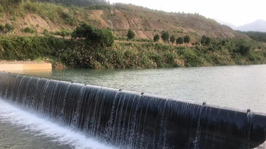
An advanced hydraulic structure — also known in the industry as a pneumatically operated spillway gate or air bladder gate — combining the merits of the rubber dam and the steel gate, with a continuously adjustable water-retaining height and operating status.
A pneumatic spillway gate consists of a group of shield plates, a group of air bags, a row of foundation anchor bolts and a set of pneumatic charging and discharging equipment. The steel shield plates take the water load and fully protect the rubber bag, while the bag provides sufficient cushioning force — combining the simplicity of a rubber dam with the durability of a steel gate.
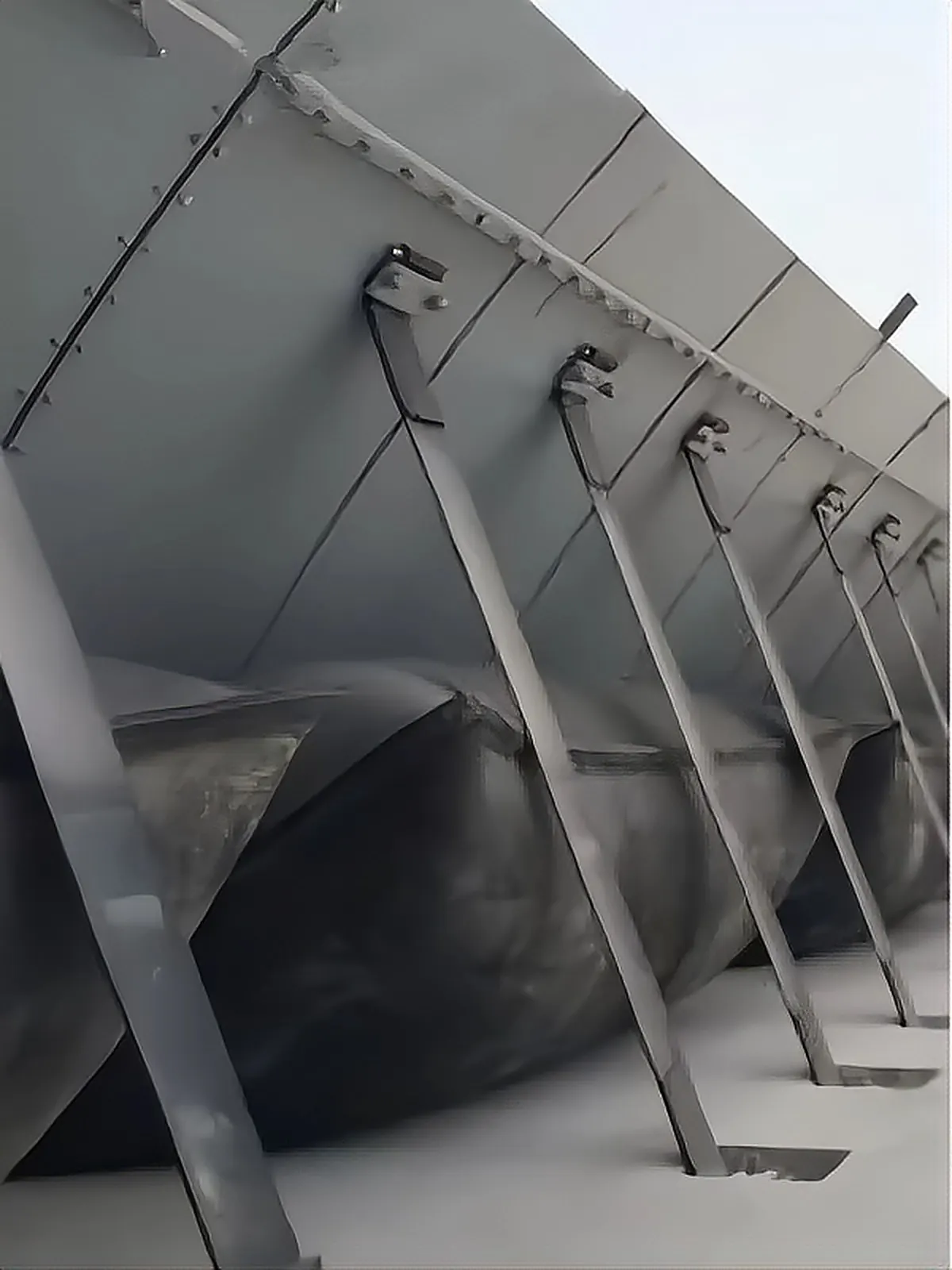
Every air shield dam ships as standardized modules — what arrives on site is what gets assembled, with no large construction equipment required.
The load-bearing armour of the system. Curved steel plates face the upstream water load and shield the rubber bag behind them from floating debris, fallen trees and ice impact. Plates hinge on the foundation line, so the crest rises and falls with the bag instead of sliding — no guiding wheels, no jamming, no card-hanging in service.
The lifting element. Air bags sit between the shield plates and the foundation; inflating them raises the plates, exhausting lets them lower. Because the bag works in a protected, low-stress state behind the steel, it is never exposed to direct impact — the working condition that limits the life of a conventional exposed dam bag simply does not exist here.
The fixing line. A continuous row of anchor bolts ties the plates and bags to the concrete sill, with a designed safety factor of 3 × the radial strength of the dam bag. Double nuts are recommended at installation, and pull-out and shear test reports can be provided on request.
The control element. A charging and discharging unit feeds or vents air to the bags, moving the crest between fully collapsed and fully raised in minutes — and holding it at any intermediate level. Level control is continuous and repeatable, which is what urban rivers and precise water-supply schemes actually need.
Raising: the charging system feeds air to the bags; the bags inflate and push the shield plates up about the hinge line until the target crest level is reached.
Holding: air pressure is maintained, and the crest stays exactly where it was set — at full height or at any intermediate position for staged release during flood season.
Lowering: exhausting the bags lets the plates rotate down onto the foundation. Fully collapsed, the shield plate adheres to the sill and the residual water-retaining height is less than 9 cm — close to the discharge capacity of an open channel, so flood peaks and heavy sediment loads pass the dam almost unobstructed.
Because the cycle is purely pneumatic, it repeats without wear-producing mechanical contact between moving steel parts — the root cause of gate-maintenance cost is designed out.
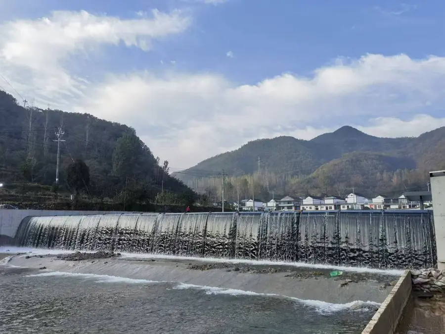
Modular structure without large construction equipment — saving manpower, material and cost with a short construction period.
The steel shield plate fully protects the rubber bag, which provides enough cushioning force and is not afraid of large floating objects.
Dam crest overflow forms a beautiful waterfall effect, enhancing the urban waterfront scenery.
No card-hanging during operation and no need for frequent maintenance or repair.
When fully collapsed the shield plate adheres to the foundation — residual water-retaining height is less than 9 cm.
Soft connection between shield plate and foundation — no system failure caused by foundation deformation.
Suitable for rivers with complicated hydrological conditions and for urban beautification projects. It can also be applied directly to the retrofit of existing rubber dams and automatic flap-gate dams.
Compared with a conventional rubber dam, the air shield dam is especially advantageous in the following situations:
Standard engineering features on every unit we deliver — not optional extras.
A high-damping shock-absorbing buffer module cushions the shield plate as it collapses, reducing the instantaneous impact on the shield and the foundation and preventing ground and plate damage.
The side stop sealing strips carry an L-shaped high-elastic return spring clip that adapts to wall flatness, improving the seal fit and preventing side-wall leakage — and keeping the strip from curling as the dam raises and collapses.
Air bag embedment uses an M-shaped pressure plate structure, forming a two-line force-bearing, point-positioned anchoring form that eliminates the risk of high-pressure air bag dislocation.
Our high-pressure air bags have a smooth, flat surface. Compared with traditional pitted bags, friction is reduced, aquatic plants adhere less easily and the appearance is neater — extending bag service life.
Air bag bolt openings adopt anti-deformation technology, keeping the openings in shape through long-term inflation, preventing bag slippage and raising the safety factor.
Shield plates receive hot-dip galvanizing plus a topcoat of sealing paint to prevent rust and extend service life; anchor bolts and pre-embedded plates are galvanized or zinc-infiltrated for corrosion protection.
Every dam comes with inclinometers, liquid level gauges and pressure sensors, monitoring shield operating angle, air bag pressure and river water level in real time — with a Baoli integrated control cabinet and remote-control operation interface.
Level one: raw material incoming inspection (chemical analysis + mechanical performance testing). Level two: in-process inspection during production. Level three: factory inspection of every product before delivery.
Debris load, ice period, wide river span or retrofit constraint — tell us your river conditions and target crest height, and our engineers will confirm the right configuration for your project. Contact our engineering team →
Before delivery, every high-pressure air bag undergoes a maximum load-bearing pressure test. The bags burst only at 1.3 MPa — more than three times the maximum actual operating pressure of 0.04–0.4 MPa — guaranteeing a wide safety margin for decades of cycling.
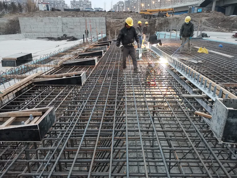
Three phases — foundation, bag & plates, sealing & commissioning. The modular structure keeps the site sequence short and light — no large construction equipment required. Real photos from our installation sites.
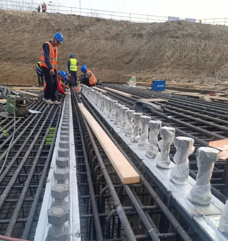
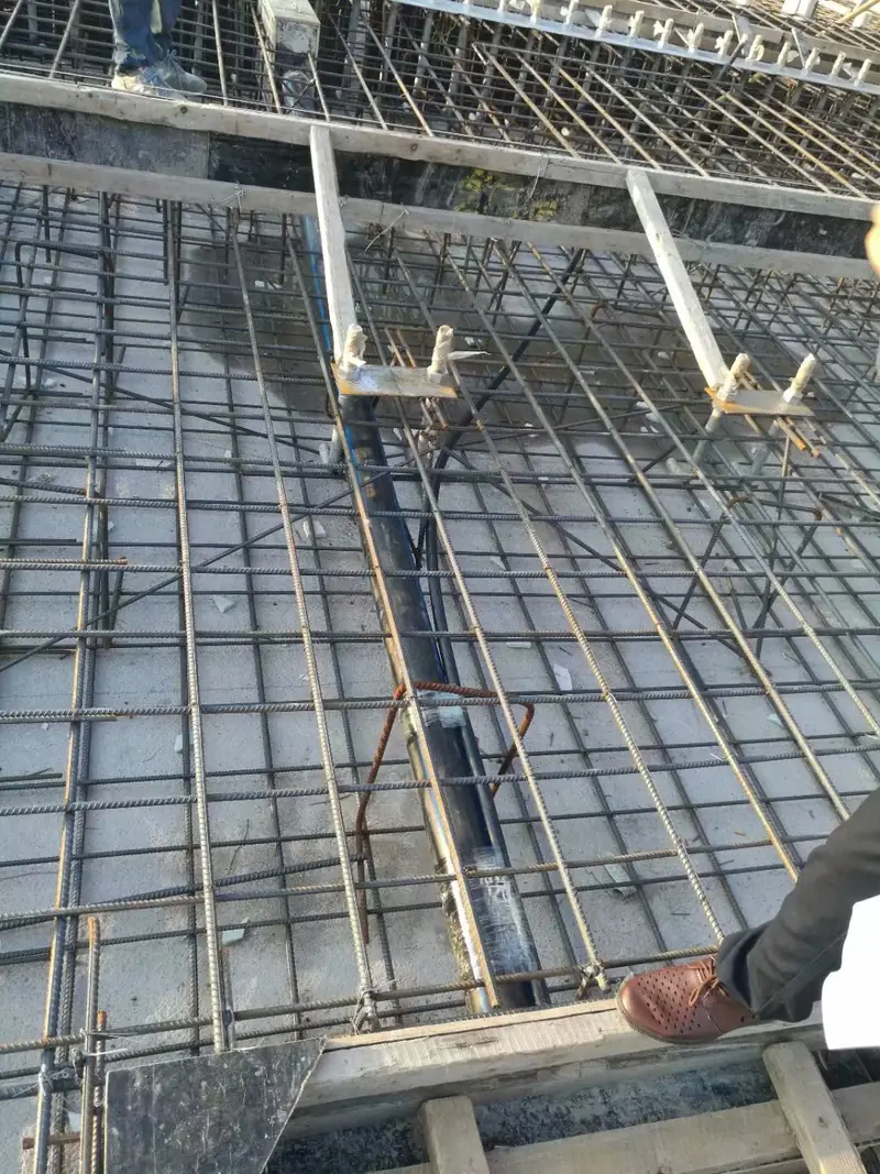
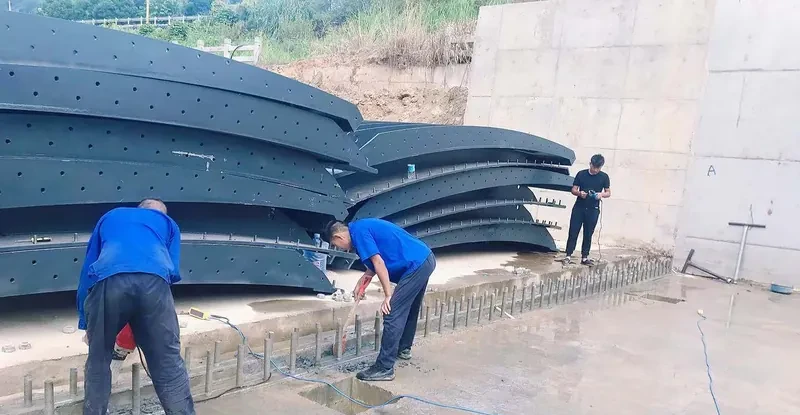
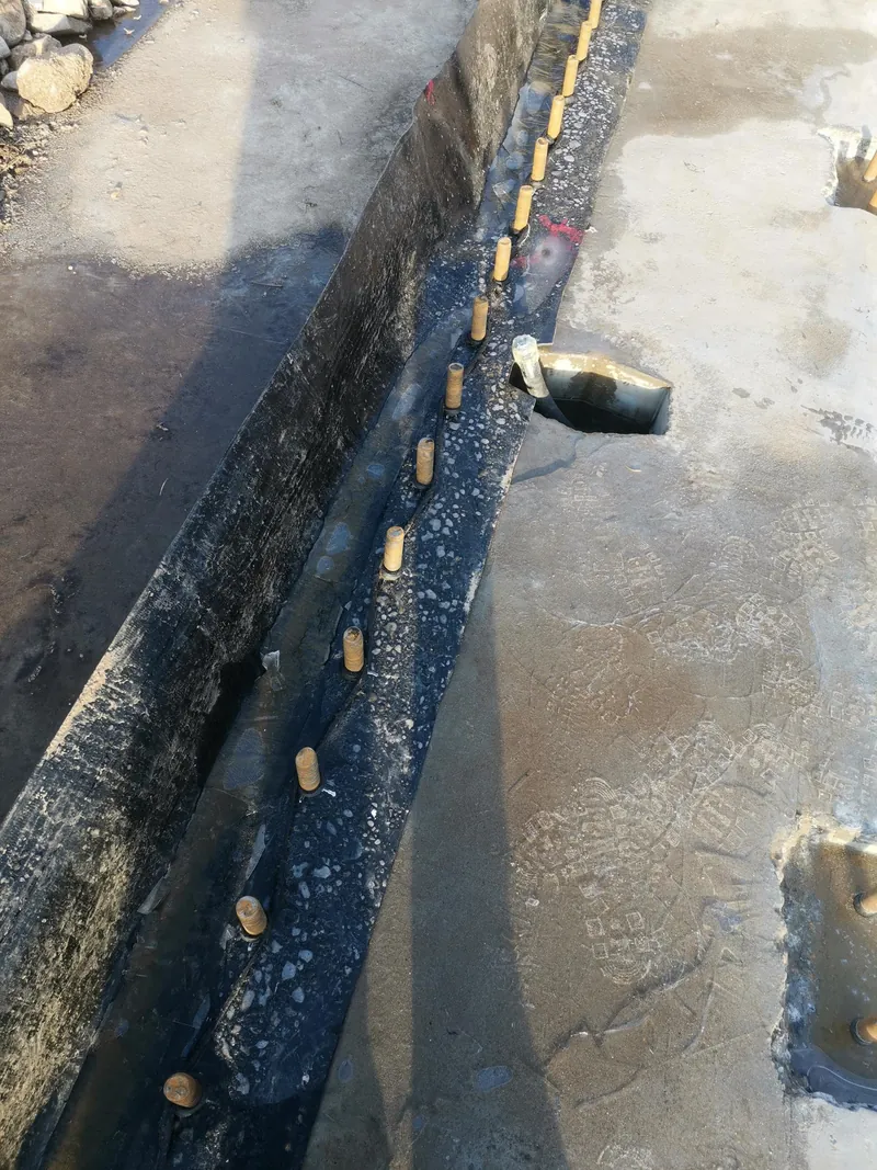
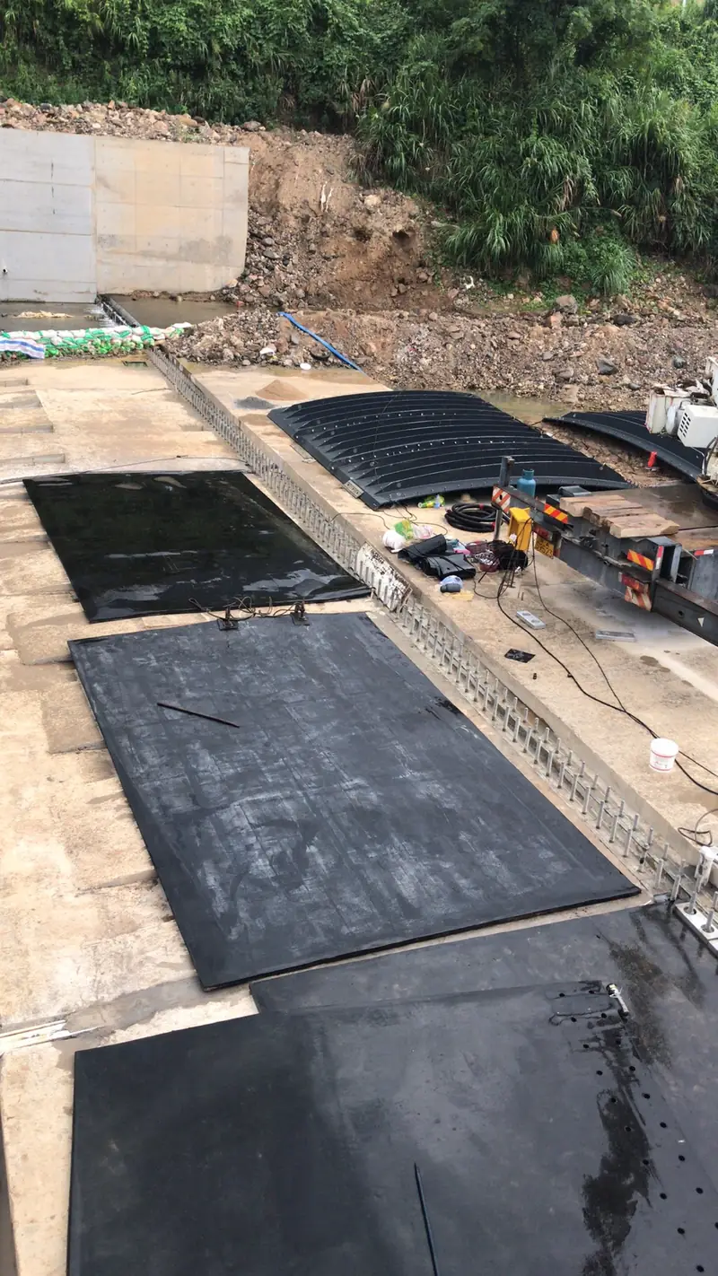
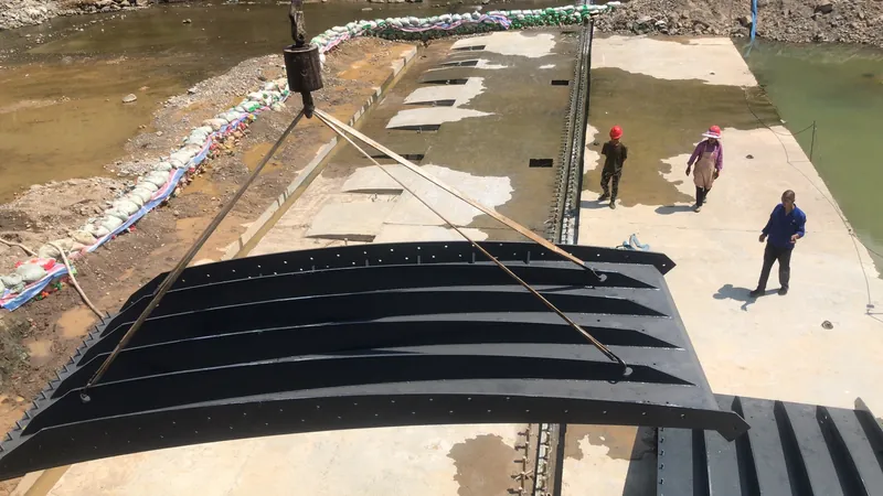
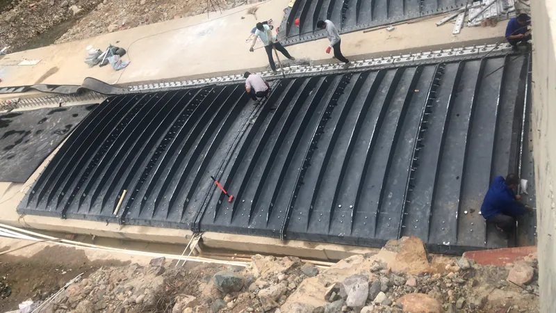
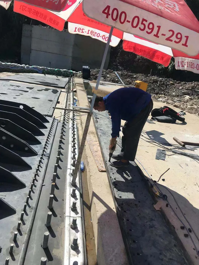
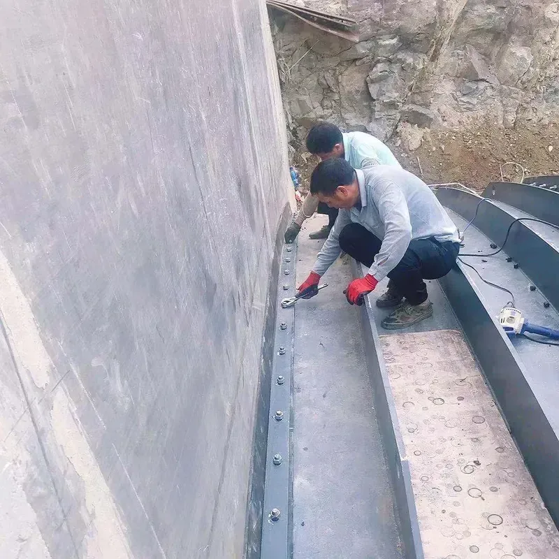
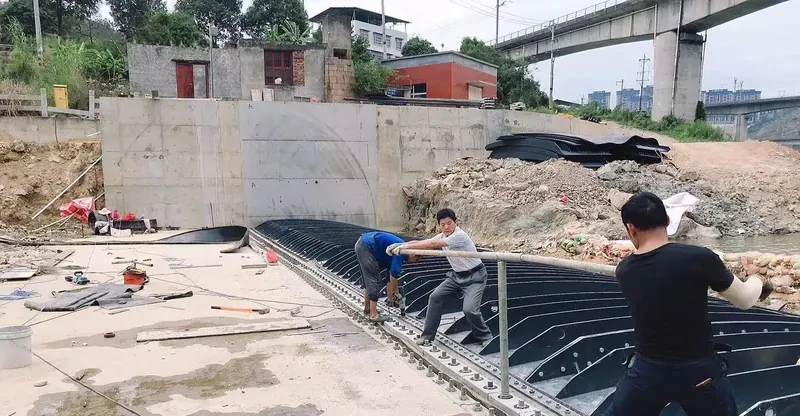
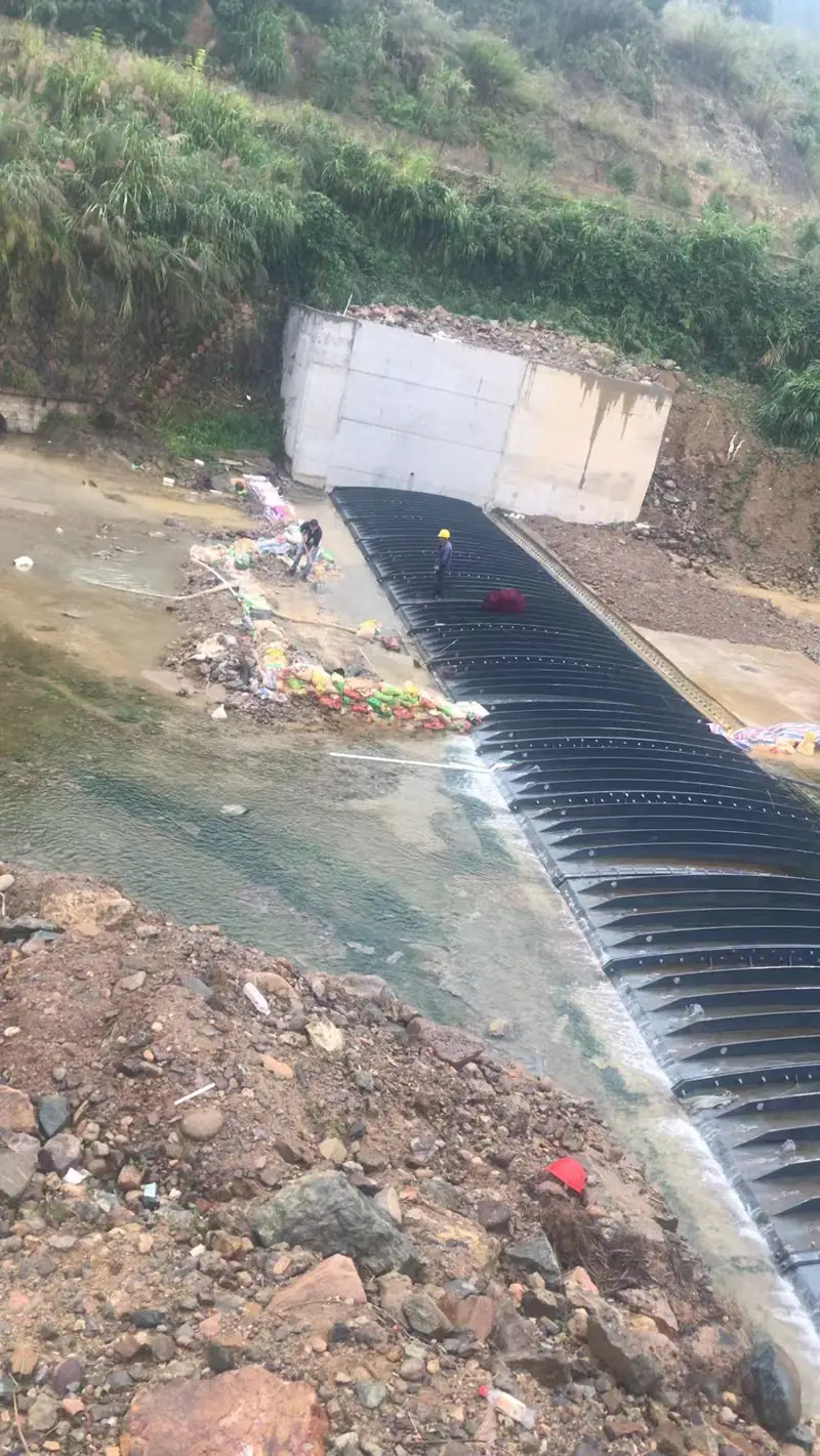
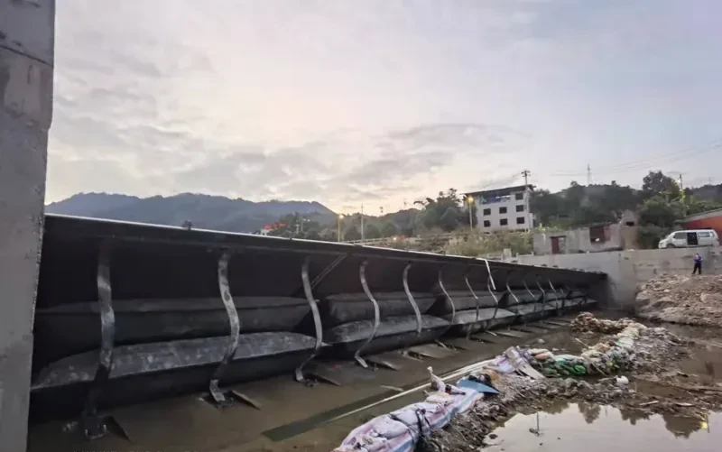
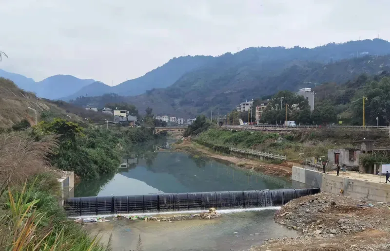
The same water-retention function, with a different answer to debris damage and sediment deposition.
| Item | Air Shield Dam | Conventional Rubber Dam |
|---|---|---|
| Bag Protection | Steel shield plates fully protect the bag | Bag is directly exposed to debris and impact |
| Residual Retention | < 9 cm after full collapse | Higher residual rubber height |
| Level Adjustment | Continuously controllable crest height | Stepwise, less granular |
| Maintenance | No card-hanging, low maintenance | Periodic bag inspection and repair |
| Foundation Fit | Soft connection, tolerant of deformation | Rigid anchorage |
| Retrofit | Direct upgrade for old rubber and flap-gate dams | Usually requires full replacement |
In practice the choice tracks the site rather than the catalogue: shield plates pay for themselves where debris, sediment or ice load the bag — see which dam type is specified for which sector. The steel-gate end of the same spectrum is set out in rubber dam vs steel gate, on nine criteria.
| Parameter | Standard Value | Notes |
|---|---|---|
| Water-retaining height | 0.5 – 6 m | Customizable to project hydraulics |
| Upper pressure plate (standard module) | 996 mm | Standard module width |
| Lower base plate (standard module) | 998 mm | Standard module width |
| Anchor bolt spacing | 200 mm | Continuous fixing line along the sill |
| Anchor bolt safety factor | 3 × bag radial strength | Double nuts recommended at installation |
| Collapsed residual height | < 9 cm | Full collapse; near-open-channel discharge |
| Level adjustment | Continuous, pneumatic | Any intermediate crest position |
| Air bag operating pressure | 0.04 – 0.4 MPa | Continuously adjustable by charging system |
| Air bag factory pressure test | Burst at 1.3 MPa | Maximum load-bearing test before delivery |
| Quality documentation | Pull-out & shear tests | Available on request |
All values above are standard-module parameters; project-specific dimensions are confirmed at drawing stage. Send us your river width and target crest level and we will confirm the module configuration for your site.
Selected installations with their key dimensions — from single-bag urban weirs to multi-dam river schemes and cold-region projects at −30 °C Altay.
| Project | Dam Height | Dam Length | Notes |
|---|---|---|---|
| Sihong County, Suqian, Jiangsu | 5.0 m | 54 m | Double-bag air shield dam |
| Yongtai, Fujian | 4.0 m | 41 m | — |
| Zhongjiang County, Deyang, Sichuan | 3.7 m | 160 m total | 3 dams |
| Xiaogan, Hubei | 3.0 m | 185 m total | 3 dams |
| Nanping, Fujian | 3.0 m | 15 m | — |
| Gu’an, Langfang | 2.5 m | 20 m | — |
| Jinling University, Nanjing | 2.0 m | 10 m | Single air bag |
| Xiaoheihe | 2.0 m | 24 m | — |
| Altay, Xinjiang | 1.8 m | 60 m | Cold-region operation |
| Taishan, Guangdong | 1.8 m | 28 m | — |
| Lindun River, Fujian | 1.5 m | 42.5 m | — |
| Kaiyuan, Liaoning | 1.5 m | 50 m | — |
| Dandong, Liaoning | 1.5 m | 40 m | — |
| Changchun Jiutai | 1.5 m | 22 m | — |
| Gaoyang | 1.5 m / 2.8 m | 40 m / 15 m | Dam 3# and Dam 4#, one set each |
Heights and lengths as delivered for each project; module configuration is confirmed per site hydraulics. Ask for reference details close to your project conditions.
Click any photo to enlarge.
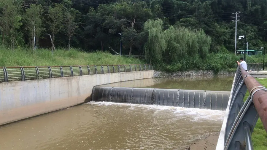
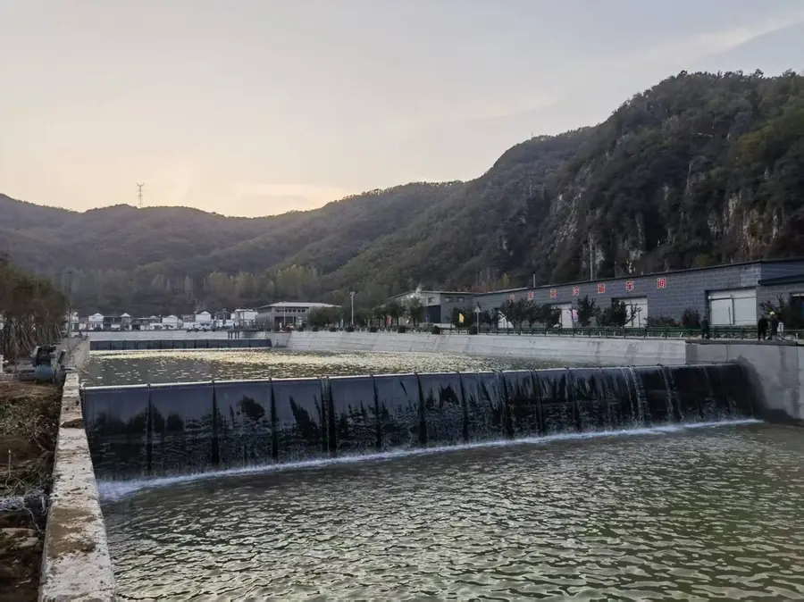
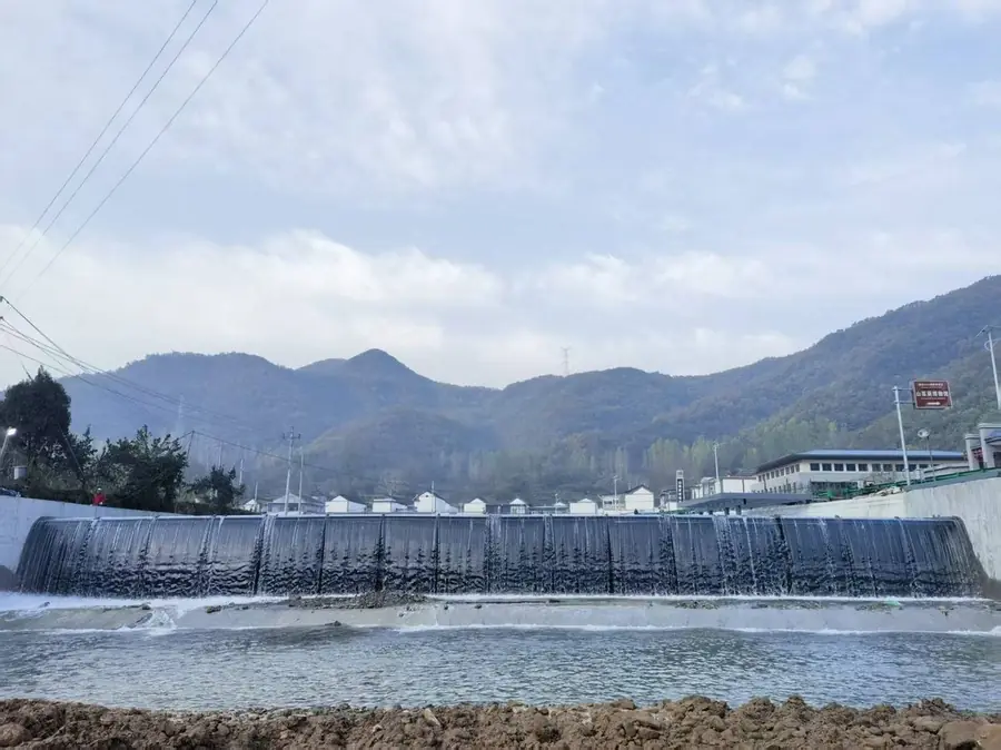
The air shield dam can be applied directly to the transformation of existing rubber dams and automatic flap-gate dams. Send us your current dam parameters for a retrofit assessment. Retrofit scope, control systems and spare parts are covered in the air shield dam FAQ.